Search  for anything...

MakerFocus 2pcs ESP8266 NodeMCU LUA CP2102 ESP-12E Internet WiFi Development Board Serial Wireless Module Internet for Ar duino IDE/Micropython with Free Adapter Board for ESP8266 ESP-01 and nRF24L01+

  • Based on 428 reviews
Condition: New
Checking for product changes

Buy Now, Pay Later


As low as $3 / mo
  • – 4-month term
  • – No impact on credit
  • – Instant approval decision
  • – Secure and straightforward checkout

Ready to go? Add this product to your cart and select a plan during checkout. Payment plans are offered through our trusted finance partners Klarna, PayTomorrow, Affirm, Afterpay, Apple Pay, and PayPal. No-credit-needed leasing options through Acima may also be available at checkout.

Learn more about financing & leasing here.

Free shipping on this product

This item is eligible for return within 30 days of receipt

To qualify for a full refund, items must be returned in their original, unused condition. If an item is returned in a used, damaged, or materially different state, you may be granted a partial refund.

To initiate a return, please visit our Returns Center.

View our full returns policy here.


Availability: In Stock.
Fulfilled by Amazon

Arrives Wednesday, Nov 27
Order within 18 hours and 14 minutes
Available payment plans shown during checkout

Features

  • User manual: Please get the link from the product description below
  • The chip model: CP2102
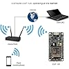
  • ESP8266 is a highly integrated chip designed for the needs of a new connected world. It offers a complete and self-contained Wi-Fi networking solution, allowing it to either host the application or to offload all Wi-Fi networking functions from another application processor
  • ESP8266 has powerful on-board processing and storage capabilities that allow it to be integrated with the sensors and other application specific devices through its GPIOs with minimal development up-front and minimal loading during runtime. Its high degree of on-chip integration allows for minimal external circuitry, and the entire solution, including front-end module, is designed to occupy minimal PCB area

Description

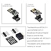
Color:2pcs CP2102 Instruction & Steps of How to use:There is the way to guide you to use the new version: The command you needed to use is: esptool.py --baud 115200 --port /dev/tty.SLAB_USBtoUART write_flash -fs 32m -ff 80m --flash_mode dio 0x00000 boot_v1.7.bin 0x1000 user1.bin 0x37c000 esp_init_data_default.bin 0x37e000 blank.bin The important part is “—flash mode dio” 1. Download the Ar duino IDE, the latest version. 2. Install the IDE 3. Set up your Ar duino IDE as: Go to File->Preferences and copy the URL below to get the ESP board manager extensions: Placing the http:// before the URL lets the Ar duino IDE use it...otherwise it gives you a protocol error.4. Go to Tools > Board > Board Manager> Type "esp8266" and download the Community esp8266 and install. 5. Set up your chip as:Tools -> Board -> NodeMCU 1.0 (ESP-12E Module)Tools -> Flash Size -> 4M (3M SPIFFS)Tools -> CPU Frequency -> 80 MhzTools -> Upload Speed -> 921600Tools-->Port--> (whatever it is)6. Download and run the 32 bit flasher exe at Github(Search for nodemcu/nodemcu-flasher/tree/master/ at Github) github.com/nodemcu/nodemcu-flasher/tree/master/Win32/Release Or download and run the 64 bit flasher exe at: github.com/nodemcu/nodemcu- flasher/tree/master/Win64/Release7. In Ar duino IDE, look for the old fashioned Blink program. Load, compile and upload. 8. Go to FILE> EXAMPLES> ESP8266> BLINK, it will start blinking. Item-type: Electronics › Computers & Accessories› Networking Products › Network Transceivers Package Including2 ESP8266 ESP-12E NodeMcu Development Board1 “nRF24L01+” and ESP8266 ESP-01 Breadboard Breakout Adapter Board(for free)


Product Dimensions: 1.9 x 0.9 x 0.2 inches


Item Weight: 0.6 ounces


Manufacturer: MakerFocus


Item model number: 4328612740


Is Discontinued By Manufacturer: No


Date First Available: July 16, 2016


Frequently asked questions

If you place your order now, the estimated arrival date for this product is: Wednesday, Nov 27

Yes, absolutely! You may return this product for a full refund within 30 days of receiving it.

To initiate a return, please visit our Returns Center.

View our full returns policy here.

  • Klarna Financing
  • Affirm Pay in 4
  • Affirm Financing
  • Afterpay Financing
  • PayTomorrow Financing
  • Financing through Apple Pay
Leasing options through Acima may also be available during checkout.

Learn more about financing & leasing here.

Top Amazon Reviews


  • Great for Learning and Protyping ESP8266
Color: 2pcs CP2102
I purchased this pair of boards and, overall, I am very pleased with my purchase. They arrived well packaged with the boards in individually sealed, anti-static bags. Inside each bag, the board was pressed into a foam sheet to protect the pins from damage. I have worked a lot with static sensitive electronic devices, and these were well packaged for optimum protection. Although I haven’t done extensive testing with the boards yet, I did verify that both are functional. They came with the NodeMCU “AT” firmware loaded, but I use them with the Arduino environment and load ‘sketches’ to them. There is no documentation provided with the boards, but I think that most of the buyers of these boards are pretty adept at finding documents on the internet. Using Windows 10 Home edition, the Silicon Labs CP210x USB driver loaded automatically. I think Win10 downloaded the driver from the internet because the search & loading process took about 60 seconds. Once the driver is loaded, connection time to the PC is nearly immediate upon plugging into the USB port. A little experimentation with different micro-USB cables confirmed that cable length does matter. Although the module receives power and will function on a longer cable, getting the device recognized as a COM device with a cable longer than 3-feet (1 meter) is not reliable. Some of my 6-foot cables worked, and some did not. I recommend cables of 3-ft or less for programming and debugging. I only tested the COM port speed at 115.2Kbps and 230.4Kbps; both worked fine. I did not try to load sketches faster than 115.2Kbps. I was not finding any information on which “board” to select in the Arduino environment, so I chose “NodeMCU 1.0 (ESP-12E Module)” and it seems to work perfectly. After loading programs that generate web pages to control I/O pins, both boards connected quickly with my home network. In addition to securely connecting to my home network, I also have the boards set to simultaneously act as Wi-Fi “access points”. The default access point name is “AI-THINKER_” followed by the last six characters of the device’s MAC address. If you let your PC connect to it, the module will provide your PC with an IP address (yep, these things have onboard DHCP service) and you can access your web page(s) by pointing your web browser to 192.168.4.1. I have not looked into whether the access point name or IP are changeable, but the IP settings for the module’s connection to my home network are easily changeable. One of things that I especially like about these particular boards is that all of the pins are clearly labeled on both sides of the circuit board. This makes prototyping much easier as you are not constantly looking at a pinout diagram and then counting pins on the board to make sure you are wiring to the correct pin. I like that the board has “FLASH” and “RST” buttons, and they are clearly labeled. All labeling is silk screened onto the circuit board, and appears to be quite durable. For those who have not used ESP-12E modules, there is a blue LED next to the antenna on the actual ESP-12E. This LED is primarily there as an indicator that the board is communicating serially with the PC, so you should see it flashing when you are downloading a program or using serial communication with the board. This LED is actually connected to GPIO2, so if you configure that pin to be an output then you can also turn the LED ‘ON’ and ‘OFF’ with your program. It is a great way to flash status codes from your prototype program. I know this review is long, but it is the type of information I look for when deciding whether or not to buy something I am considering buying. ... show more
Reviewed in the United States on November 24, 2016 by Ed K.

  • Finally got it to work!
Color: 2pcs CP2102
This product suffers from a severe lack of documentation. After days of fiddling I have finally gotten it to work with the Arduino environment. To help those who are having problems, here are the steps necessary to make it work with the Arduino programming environment. 1) Download the latest Arduino environment (use Google). I am using 1.8.3 on Windows 7. 2) Follow the guide on sparkfun regarding installing the 8266 in the arduino environment. Google "sparkfun installing 8266 guide" and it should be the top link. 3) You must also have the Silicon Labs CP210x USB to UART Bridge driver installed (probably need to reboot). It is available for most major OS's. Use Google to find the driver. Verify that (in windows) your Device Manager lists this driver in the PORTS part of the tree. It will also show your COM port for your ESP8266 next to it. If it doesn't show, then nothing else will work. 4) Now in the Tools menu you will need to setup for your board. Everything after this is under the Tools menu in the Arduino environment. Set Board -> Generic ESP8266 Module Set Flash Mode -> DOUT Leave Upload Speed -> 115200 6) Hold the flash button on the board while uploading the code from the Arduino environment. I suggest the back side of a pencil since you will be holding it a while. 7) Click reset on the board to start the program. Here is a sample blink program I know works and blinks the blue LED on the board its self. One last tip, the labels for the pins are correct on the bottom of the board, but oddly the top of the board does not seem to map correctly (might be me not understanding why D0 is supposed to equal GPIO16). So GPIO0 on the bottom is actuated by digitalWrite(0,HIGH) in the code. int PIN = 2; void setup() { pinMode(PIN, OUTPUT); digitalWrite(PIN, LOW); } void loop() { digitalWrite(PIN, HIGH); delay(1000); digitalWrite(PIN, LOW); delay(1000); } ... show more
Reviewed in the United States on June 17, 2017 by Zeeri

  • Great boards!! Once you figure them out...
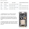
These boards are an incredible value!! Having the integrated Wifi makes building IOT projects extremely easy to complete. There are a couple of issues that I struggled with at first: - The pin numbers are a little confusing, when programming using the Arduino IDE insert this code at the beginning of your sketch to convert from the Dx pin numbers printed on the board to pin numbers that Arduino recognizes. //ESP 8266 PIN OUTS #define D0 16 #define D1 5 // I2C Bus SCL (clock) #define D2 4 // I2C Bus SDA (data) #define D3 0 #define D4 2 // Same as "LED_BUILTIN", but inverted logic #define D5 14 // SPI Bus SCK (clock) #define D6 12 // SPI Bus MISO #define D7 13 // SPI Bus MOSI #define D8 15 // SPI Bus SS (CS) #define D9 3 // RX0 (Serial console) #define D10 1 // TX0 (Serial console) - In addition, the V3 boards are too wide to use on a standard width breadboard. If you use two breadboards side by side you can solve this problem and have plenty of space for your projects. I have attached a photo that shows how I did it. ... show more
Reviewed in the United States on March 1, 2017 by David Millar

Can't find a product?

Find it on Amazon first, then paste the link below.